 EN

Matching Transformer Voltage and Grid Requirements APEX TECHNOLOGIES | Transformer Buying Guide
A transformer ratio must fit both the source and the connected system. Two units described as “11 kV to 400 V” may still differ in frequency, insulation level, winding connections, neutral arrangement, impedance and taps. Those differences can determine whether a unit works correctly in a new installation or alongside existing equipment.
Define Both Sides of the Connection
Identify the nominal network voltage, normal operating range, required load voltage, frequency and phase arrangement. For a generation or storage connection, also state the direction of power flow and any intended bidirectional operation. The high-voltage winding is not always the input winding: an LV-to-MV step-up transformer takes input on its low-voltage side.
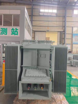
Photo 1. Transformer terminal-compartment workshop view. Winding voltage, connection group and neutral availability must be confirmed from the nameplate and connection diagram, not terminal appearance alone.
Use the Correct Voltage Reference
In a balanced star system, line-to-neutral voltage is line-to-line voltage divided by √3. Thus 400 V line-to-line corresponds to approximately 230.9 V line-to-neutral. The three-phase capacity formula uses line-to-line voltage and line current. A delta winding does not inherently provide an accessible neutral; a requirement for four-wire loads must be addressed in the actual connection arrangement.
Separate Ratio from Insulation and Frequency
|
Specification item |
What it establishes |
|
Rated winding voltages |
The specified winding voltage ratio and its reference tap. |
|
System operating range |
The voltages expected at the site during normal operation. |
|
Highest voltage for equipment |
An insulation-class characteristic; not simply the winding ratio. |
|
Dielectric withstand requirements |
Specified power-frequency, impulse and any other required insulation tests. |
|
Frequency |
The system frequency at which the offered unit must operate. |
|
Vector group and neutral |
Winding connections, displacement and whether a neutral terminal is provided. |
An 11 kV Network Is Not Just an “11 kV” Label
A utility specification may associate an 11 kV network with a 12 kV highest voltage for equipment and defined withstand levels. That is an example of distinguishing system voltage from insulation class, not a universal insulation schedule for every country or installation. Obtain the project requirements, including earthing, surge conditions and altitude, before accepting the offered insulation basis.
A Transformer Does Not Convert Frequency
A passive transformer changes voltage but not supply frequency: a 50 Hz source remains 50 Hz on the other side. A machine needing another frequency requires an appropriate conversion arrangement, not simply a different transformer ratio. Confirm that the offered transformer is rated for the actual supply frequency and voltage.
Do not assume a 60 Hz-only design can operate at unchanged voltage on a 50 Hz supply. The voltage-to-frequency ratio affects magnetic flux, while losses, cooling and usable output also require assessment. Any alternative-frequency use must be confirmed by the manufacturer for the actual configuration rather than inferred from a simple percentage rule.
State Voltage Tolerance at the Correct Location
A transformer terminal voltage is not necessarily the voltage at a distant motor or inverter. The transformer regulation and cable drop both matter. Define where voltage must be maintained and under which loading and power-factor conditions, so the transformer ratio is not used to conceal an unresolved distribution voltage-drop problem.
Select Taps for the Operating Requirement
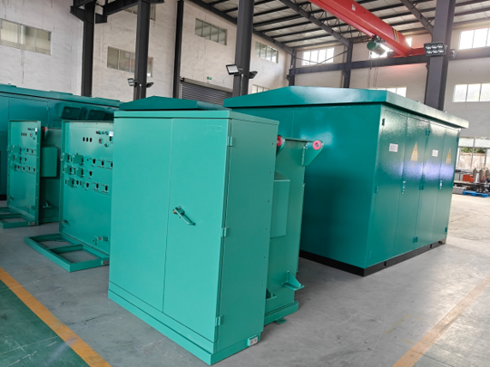
Photo 2. Enclosed transformer equipment from the APEX product page. Tap arrangement and permissible operation are defined by the approved equipment documentation; the voltage example below is illustrative.
In the idealized example, a transformer rated 11 kV/400 V produces about 380 V at no load if supplied at 10.45 kV on its nominal tap. If its approved tap schedule includes a 10.45 kV rated tapping, selecting that tapping restores the ideal no-load output to 400 V. Actual loaded output still depends on impedance, load power factor and downstream voltage drop.
Off-Circuit and On-Load Tap Changing
An off-circuit or de-energized tap changer is adjusted only under the manufacturer’s specified isolated and de-energized conditions. An on-load tap changer is specifically designed to change taps during energized operation. Specify which function is needed; a list of percentage taps does not establish an on-load capability.
Use the manufacturer’s tap schedule and terminal instructions. A tap marked “plus” usually describes a winding rated-voltage position, not a universal instruction that the secondary will increase. The effect depends on the energized winding, the chosen tapping and the operating arrangement.
Avoid Treating Taps as a Universal Cure
Taps provide a defined range of ratio adjustment. They do not change frequency, correct an incompatible phase displacement or create adequate conductor capacity. For a supply that varies substantially during operation, establish the required regulation strategy, control range and interaction with other voltage-control equipment.
Coordinate Connections Impedance and Protection
Read the Vector Group as an Electrical Requirement
In a designation such as Dyn11, D identifies the HV delta connection, y the LV star connection, and n an accessible LV neutral. The clock number identifies the relative phase displacement. The designation is not a general quality grade, and another clock number is not automatically interchangeable. Protection, phase identification and existing connections need to match the actual arrangement.
Earthing and the Neutral Need Their Own Review
Bringing out a neutral terminal does not define how the system is earthed. Solid, resistance and other earthing arrangements affect fault behaviour, protection and insulation requirements. Unbalanced and nonlinear loads can also affect neutral duty. Specify the intended system arrangement rather than adding a neutral terminal as a last-minute accessory.
Impedance Changes More Than the Purchase Specification
Transformer impedance influences voltage drop, short-circuit current and load sharing. Lower impedance is not always better: it can increase available fault current and change switchgear requirements. Higher impedance can reduce fault contribution while increasing voltage variation for a given load and power factor.
For an illustrative 1,000 kVA, 400 V three-phase transformer with 6% impedance, rated LV current is approximately 1,443.4 A. With an ideal infinitely strong upstream source, a simplified terminal-fault estimate is 1,443.4 / 0.06 ≈ 24.1 kA. This estimate omits upstream and cable impedance, motor contribution, tolerances and other study factors. It must not be used alone to select switchgear or protection.
Parallel Operation Is a System Decision
Check voltage ratio and tap positions, winding connections and phase displacement, phase sequence, impedance and load sharing. Include the impedance of connections to the common bus. Units with the same voltage label can still share load poorly or be incompatible. Energization, protection settings and the resulting bus fault duty also require review.
Step-Up and Bidirectional Service
A transformer intended for reverse or bidirectional power flow needs confirmation of ratio, taps, terminals, earthing, protection and thermal duty for that operation. Do not assume that swapping the source and load connections produces an acceptable installation. Converter-connected equipment can add harmonic and operating requirements beyond nominal voltage matching.
Worked Grid-Matching Review
Illustrative requirement: an industrial replacement needs an 11 kV supply connection, a 400/230 V four-wire output and compatibility with an existing transformer. The rating alone cannot establish a suitable replacement. The review should identify the supply range, actual frequency, insulation schedule, voltage ratio and taps, vector group, neutral and earthing arrangement, impedance, terminals and existing protection interfaces.
|
Question |
Reason for checking |
|
Is the supply 50 Hz or 60 Hz? |
Frequency is not converted by the transformer. |
|
Is 400 V line-to-line required? |
This differs from a 400 V phase-to-neutral requirement. |
|
Is parallel operation planned? |
Ratio, displacement, impedance and connection compatibility need review. |
|
What is the supply range? |
Tap arrangement and loaded voltage performance must suit the site. |
|
What is the fault duty? |
Transformer impedance and upstream conditions affect equipment ratings. |
Three Common Purchasing Errors
First, specifying only primary and secondary voltages and leaving frequency or vector group unresolved. Second, copying the old nameplate without checking changed grid and load conditions. Third, assuming a tap range or neutral terminal solves voltage regulation, earthing and protection simultaneously. Each requirement needs a defined technical basis.
Information to Include in the Inquiry
Provide the single-line diagram, source and load voltage references, normal supply range, frequency, earthing arrangement, required winding connections, fault information and utility specification. For a replacement or parallel unit, include the existing nameplate and test or impedance data. Ask the supplier to identify technical deviations explicitly in the offer.
Technical References
Schneider Electric — Voltage adjustment taps
https://www.se.com/us/en/faqs/FA120846/
Schneider Electric — Transformers do not change frequency
https://www.se.com/us/en/faqs/FA115747/
Schneider Electric — Parallel transformer operation
https://www.electrical-installation.org/enwiki/Substation_including_generators_and_parallel_operation_of_transformers
National Grid — Example utility transformer specification
https://www.nationalgrid.co.uk/downloads-view-reciteme/605467
Eaton — Transformer technical data
https://www.eaton.com/content/dam/eaton/products/low-voltage-power-distribution-controls-systems/transformer/files/transformer-distribution-catalog-volume-2-tab-ca08100003e.pdf
Numerical examples are illustrative; they do not specify the photographed equipment or constitute an approved installation design.
Photos: APEX project workshop photographs and the APEX product pages listed below where applicable.
https://www.apex-electrics.com/three-phase-pad-mounted-transformer