 EN

Transformer Capacity and Current Calculations APEX TECHNOLOGIES | Transformer Buying Guide
Transformer sizing begins with apparent power and operating duty. Electrical loads may be described in kW, kVA, amperes or motor output power, and these values cannot be used interchangeably. A correct calculation identifies the units, the voltage reference and the side of the transformer being considered.
The Essential Quantities
|
Quantity |
Meaning |
|
kW |
Active electrical power consumed or exported. |
|
kVA |
Apparent power carried by the electrical system. |
|
MVA |
1 MVA = 1,000 kVA. |
|
Power factor PF |
Active power divided by apparent power. Use the appropriate true power factor for nonlinear loads. |
|
Line current A |
Current in an external phase conductor. |
|
VLL |
Line-to-line voltage, used in the balanced three-phase formula. |
Core Equations
Single-phase: S(kVA) = V × I / 1,000
Balanced three-phase: S(kVA) = √3 × VLL × I / 1,000
From electrical active power: S(kVA) = P(kW) / PF
Single-phase current: I = S(kVA) × 1,000 / V
Balanced three-phase current: I = S(kVA) × 1,000 / (√3 × VLL)
Use volts, amperes and kVA exactly as shown. √3 is approximately 1.732. If voltage is entered in kV instead of V, the three-phase current equation becomes I = S(kVA) / (√3 × VLL(kV)). Do not mix those two unit conventions.
Do Not Apply Power Factor Twice
When electrical kW is given, divide by power factor to obtain kVA. When kVA is already known, or apparent power has been calculated from RMS voltage and current under the stated assumptions, do not divide by PF again. Motor nameplate output kW is mechanical power; it also requires efficiency to estimate electrical input.
Calculate Current on Each Side
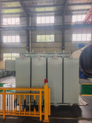
Photo 1. Radiator assemblies on an oil-immersed transformer. Physical appearance does not establish the kVA rating or allowable current; use the nameplate and approved technical data.
For a 1,000 kVA three-phase transformer, the full-load current is about 1,443.4 A at 400 V, but only 52.5 A at 11 kV. These are currents on different sides of the same power transfer. The values are not interchangeable for terminals, busbars or protection. Actual input power also includes transformer losses; the simple comparison uses the specified winding ratings.
|
Rating |
400 V |
415 V |
690 V |
11 kV |
|
250 kVA |
360.8 A |
347.8 A |
209.2 A |
13.1 A |
|
500 kVA |
721.7 A |
695.6 A |
418.4 A |
26.2 A |
|
1,000 kVA |
1,443.4 A |
1,391.2 A |
836.7 A |
52.5 A |
|
1,600 kVA |
2,309.4 A |
2,225.9 A |
1,338.8 A |
84.0 A |
|
2,500 kVA |
3,608.4 A |
3,478.0 A |
2,091.8 A |
131.2 A |
|
5,000 kVA |
7,216.9 A |
6,956.0 A |
4,183.7 A |
262.4 A |
Table values are theoretical line currents at the stated rating and voltage for a balanced three-phase system. They are not recommended breaker ratings, cable ampacities or confirmation that every listed voltage/rating combination is available.
Single-Phase Example
A 230 V single-phase load drawing 100 A requires 230 × 100 / 1,000 = 23 kVA. A suitable available transformer rating must be at least the design requirement after reviewing continuous duty, environment and any special load conditions. The three-phase √3 factor is not used for this single-phase circuit.
Build Demand from the Load Schedule
A connected-load total is not necessarily the expected simultaneous demand. Establish operating scenarios from real equipment use, measured data or the agreed design basis. Apply utilization and simultaneity assumptions to the appropriate groups; do not reduce the total repeatedly with unrelated diversity factors. For unbalanced single-phase loads, assess each phase and the neutral rather than relying only on a combined kVA value.
Worked Demand Example
|
Load group |
Assumed simultaneous demand |
PF |
Approximate kVA |
|
Process load |
400 kW |
0.90 |
444.4 |
|
Ventilation and pumping |
150 kW |
0.85 |
176.5 |
|
Lighting and general services |
80 kW |
0.95 |
84.2 |
|
Simplified arithmetic total |
630 kW |
Not a simple average |
705.1 |
The arithmetic sum of group kVA is a conservative preliminary simplification here. For sinusoidal loads, a more accurate aggregation sums active power P and reactive power Q, then uses S = √(P² + Q²). Nonlinear loads require consideration of distortion and the applicable power definitions. Do not average power factors arithmetically.
If the design explicitly allows a 15% increase in this assumed demand, the preliminary allowance becomes 705.1 × 1.15 ≈ 810.9 kVA. An available 1,000 kVA rating is a candidate at about 81.1% loading. This is an example of a stated planning assumption, not a universal rule that every installation needs 15% or must operate at 80% load.
Motor Output and Starting
For an illustrative motor with 90 kW mechanical output, efficiency 0.94 and power factor 0.88, electrical input is 90 / 0.94 = 95.7 kW and apparent input is 95.7 / 0.88 = 108.8 kVA. Use manufacturer or measured values for the actual motor. Starting current, duration, frequency of starts and permissible voltage dip require an additional review; multiplying every motor rating by a blanket starting factor is not a complete study.
Continuous and Exceptional Duty
Nameplate capacity is tied to specified operating conditions. Harmonic currents, ambient temperature, altitude, enclosure and cooling can change suitability. Temporary overload capability depends on thermal conditions and loading history; it is not spare continuous capacity that can be assumed in a purchase calculation.
Dual Windings and Cable Connections
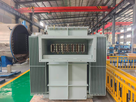
Photo 2. Terminal-compartment view of the equipment supplied as the Nigeria replacement-project reference. The calculation below is a separate hypothetical example, not a confirmed winding-capacity allocation for the photographed unit.
Consider a hypothetical 5 MVA transformer with an 11 kV winding and two 0.4 kV windings. If the technical schedule explicitly assigns 2.5 MVA to each low-voltage winding, each winding current is 2,500,000 / (√3 × 400) = 3,608.4 A. The 11 kV winding current at 5 MVA is 5,000,000 / (√3 × 11,000) = 262.4 A.
Two 0.4 kV windings do not automatically mean a 2.5 MVA/2.5 MVA split. Their ratings, permissible simultaneous loading, displacement and operating arrangements must come from the approved schedule. Combining them into one bus or paralleling them cannot be justified by equal voltages alone.
Why Cable Count Is Not a Capacity Calculation
A requirement for 32 single-core 500 mm² cables, allocated as eight each to A, B, C and N, describes a connection arrangement. It does not by itself establish transformer kVA or the current-carrying capacity of the installation. Neutral conductors are not an additional phase whose cable count can be added to increase the transformer rating.
As a purely arithmetic illustration, dividing 3,608.4 A equally among eight phase conductors gives 451.1 A per conductor. That result is not a cable selection: equal sharing depends on conductor impedances and connection arrangements, while permissible ampacity depends on cable construction, installation, grouping, temperature and the applicable design requirements. The winding to which the eight conductors connect must also be identified.
Calculation Checks Before Selection
- Confirm whether the input is electrical kW, mechanical kW, kVA or current.
- Identify single-phase or three-phase duty and the correct voltage reference.
- State power factor and efficiency assumptions; avoid applying either twice.
- Record demand, simultaneity and growth assumptions separately.
- Calculate each winding current from its own rating and voltage.
- Check starting, harmonics, unbalance, cooling and site conditions.
- Select cables, terminals and protection through their own coordinated design.
Does full-load current equal breaker size?
No. Transformer full-load current is an input to a protection study. Energization inrush, protection coordination, equipment withstand and local installation requirements also affect protective-device selection. A rounded current result is not a breaker recommendation.
Can I use one overall PF for a mixed facility?
Only if that value represents the intended operating scenario. Different load groups, control modes and compensation can change the result. Measured demand or a properly developed load schedule is preferable to an arbitrary overall factor.
Is apparent power always the only constraint?
No. A unit within its kVA rating can still have unacceptable harmonic heating, phase unbalance, voltage drop or starting performance. The calculation establishes an electrical loading basis; it does not replace assessment of the duty.
Technical References
Schneider Electric — Transformer current calculation
https://www.se.com/us/en/faqs/FA338225/
ABB — How to size a transformer
https://www.abb.com/global/en/news/138988/how-to-size-a-transformer
IEEE — Transformer loading guide
https://standards.ieee.org/ieee/C57.91/7163/
Numerical examples are illustrative; they do not specify the photographed equipment or constitute an approved installation design.
Photos: APEX project workshop photographs and the APEX product pages listed below where applicable.