 EN

How to Select a Transformer for Your Project APEX TECHNOLOGIES | Transformer Buying Guide
A transformer should be selected for the complete project, not for its kVA rating alone. The right unit must match the electrical system, carry the expected load, fit the installation and connect to the equipment on both sides. The purchase decision also needs a clear definition of tests, accessories and delivery responsibilities.
Begin with a short description of the application: what supplies the transformer, what it supplies or connects to, where it will operate, and whether the project is new construction, expansion or replacement. These answers prevent a technically plausible quotation from becoming an unsuitable installation.
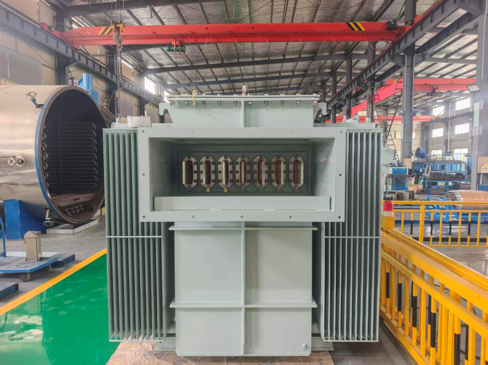
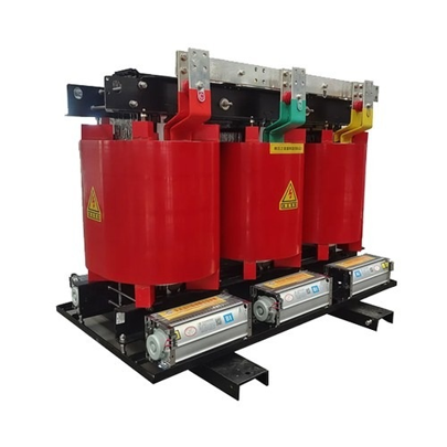
Photo 1. Oil-immersed transformer in the workshop (left) and a cast-resin dry-type transformer from the APEX product range (right). Construction, installation conditions and cooling must be considered together.
Step 1 Identify the Electrical Duty
Separate ordinary distribution from generation step-up, isolation, rectifier and other special duties. A transformer supplying a steady building load does not face the same waveform and operating profile as a unit connected to converters. A replacement also has to fit existing connections and installation constraints. State the direction of normal power flow and whether reverse or bidirectional operation is required.
Step 2 Establish the Voltage and Capacity Basis
Record the input and output voltages, frequency, phase arrangement and expected demand. Transformer capacity is normally expressed in kVA or MVA, while many load lists use kW. Power factor, simultaneity and any documented expansion plans must be addressed before selecting a rating. The following two guides explain these calculations and the grid-matching decisions in detail.
Match the Selection to the Project
|
Project |
Main selection questions |
|
Factory or industrial plant |
Motor starting, changing demand, drives, fault duty, shutdown and maintenance requirements. |
|
Commercial or residential development |
Diversified demand, phase balance, noise, fire strategy, room access and local utility requirements. |
|
Data centre or critical facility |
Nonlinear loads, redundancy strategy, cooling, neutral duty and the load carried after a unit is unavailable. |
|
PV, wind or storage |
Converter interfaces, reactive power, harmonics, power-flow direction and grid connection requirements. |
|
Remote, mining or exposed site |
Temperature, altitude, dust, corrosion, access and any applicable hazardous-area approvals. |
|
Equipment replacement |
Existing nameplate, ratio, vector group, impedance, terminals, footprint, cables and protection interfaces. |
Step 3 Choose the Construction
Oil-immersed transformers use liquid for insulation and heat transfer. Their installation may require provisions for liquid containment, fire protection and maintenance. Cast-resin and VPI dry-type transformers use different winding insulation constructions and need suitable ventilation, enclosure protection and environmental assessment. Neither the absence of oil nor a particular insulation process proves suitability for every indoor installation.
Pad-mounted and pole-mounted describe installation arrangements as well as connection and enclosure characteristics. They should not be treated as direct alternatives to any transformer with the same voltage ratio. A pad-mounted unit must match the required feed and terminal interfaces; a pole-mounted unit must match the network, mounting and utility practice.
Avoid Choosing Technology by Price Alone
Compare installation cost, losses, maintainability, space and service conditions alongside purchase price. The winding material is one design choice, not a complete measure of quality. Copper or aluminium conductors must be assessed with the guaranteed losses, temperature rise, terminal arrangement and verified performance of the actual design.
Specify the Installation and Interfaces
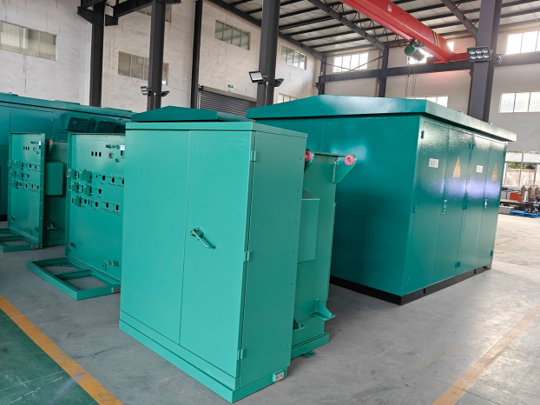
Photo 2. Enclosed equipment shown on the APEX pad-mounted transformer product page. Enclosure layout, access and connection arrangements form part of the selection.
Step 4 Describe the Site
Provide maximum and typical ambient conditions, altitude, indoor or outdoor location, condensation, dust, corrosion exposure and any noise restrictions. Do not assume a catalogue rating applies unchanged to an unusually hot, high-altitude or poorly ventilated site. The supplier should identify the performance basis and any changed rating or cooling requirement for the stated environment.
Step 5 Confirm the Physical Connections
Include cable quantities, conductor cross-sections, lug requirements, bus connections, entry direction and available working space. For a replacement, photographs are useful but approved dimensions and connection drawings remain necessary. Check access for doors, maintenance, lifting, transport and removal of the old unit before committing to a footprint.
Step 6 Coordinate Electrical Interfaces
The vector group, neutral arrangement, earthing, impedance and protection must work with the surrounding system. Check transformer energization inrush separately from load starting. Parallel operation requires a compatibility review; identical kVA labels do not establish compatible ratios, phase displacement or load sharing.
Step 7 Define the Accessory and Document Scope
Identify required temperature monitoring, protective devices, cooling controls, terminal boxes and communication signals for the chosen design. A list headed “all accessories” is ambiguous: the agreed equipment schedule should name them. Also define drawings, technical guarantees, test reports, inspection or witness points and the installation documentation included in the supply.
Worked Selection Example
Illustrative project: an industrial facility has an expected simultaneous electrical demand of 800 kW at a power factor of 0.90. Its planned expansion adds 20% to that demand. The site supply is 11 kV and the required output is 400 V, three-phase, at the locally confirmed frequency.
|
Stage |
Calculation or decision |
|
Present apparent demand |
800 / 0.90 = 888.9 kVA |
|
Demand after stated expansion |
888.9 × 1.20 = 1,066.7 kVA |
|
Candidate rating |
A 1,250 kVA unit would carry 85.3% of nameplate at this demand, before checking site and duty limitations. |
|
Voltage basis |
11 kV / 400 V; equipment insulation, taps, vector group and neutral remain separate decisions. |
|
Further checks |
Motor starting, harmonics, ambient/altitude, impedance, fault duty, ventilation and terminal arrangement. |
The example identifies a candidate, not a finished design. A 1,000 kVA unit is below the assumed expanded demand. A 1,250 kVA unit may be appropriate, but its rating must remain adequate under the actual site conditions and operating duty. A larger unit should not be selected automatically without considering cost, losses, fault contribution and the reason for additional capacity.
What Changes for a Critical Facility
If the project uses two transformers for redundancy, define the load that each must carry when the other is unavailable. Two units each selected for half the normal demand do not automatically provide full-load N−1 capability. Bus arrangements, transfer sequences and the permitted emergency duty must also support the continuity objective.
What Changes for a Replacement
The existing cable or bus interface can constrain the new unit. The existing vector group and impedance may also affect parallel operation and protection. Preserve the operational requirement, but do not copy an old nameplate without reviewing changes to loading, the grid and applicable project requirements.
Before You Accept a Quotation
- Confirm the application, rated power, voltage ratio, phase and frequency.
- Agree vector group, earthing, impedance, tap arrangement and any special load duty.
- Compare guaranteed losses and temperature-rise conditions on the same basis.
- Check enclosure, cooling, terminals, dimensions, mass and site conditions.
- Identify applicable standards and any model-specific certification separately.
- Confirm accessories, documents, tests, exclusions, delivery terms and warranty.
Is a larger transformer always better?
No. Extra capacity can increase purchase cost, physical size and no-load loss. It can also change the available fault current. Additional capacity should follow a stated load, growth or reliability requirement rather than a blanket percentage.
Does compliance with a standard mean independent certification?
No. A stated design standard and third-party certification are different. Confirm the actual model, test scope, market coverage and documents required for the project. A general certificate should not replace a technical review of the offered equipment.
What is the most useful first inquiry?
Send a load schedule, project country, source and load voltages, frequency, installation environment and any single-line diagram. For replacements, add the nameplate, outline drawing and terminal details. An early inquiry can identify undecided items; the order should resolve them through the technical schedule and agreed supply scope.
Technical References
Schneider Electric — Choice of MV/LV transformer
https://www.electrical-installation.org/enwiki/Choice_of_MV/LV_transformer
IEEE — Guide for Loading Mineral-Oil-Immersed Transformers
https://standards.ieee.org/ieee/C57.91/7163/
Schneider Electric — Transformer capacity calculations
https://www.se.com/us/en/faqs/FA101694/
Numerical examples are illustrative; they do not specify the photographed equipment or constitute an approved installation design.
Photos: APEX project workshop photographs and the APEX product pages listed below where applicable.
https://www.apex-electrics.com/cast-resin-dry-type-transforme
https://www.apex-electrics.com/three-phase-pad-mounted-transformer