 EN
EN

Three-Phase Pad-Mounted Transformer Selection: Radial vs Loop Feed, kVA and Site Layout
|
Slug |
three-phase-pad-mounted-transformer-selection |
|
Category |
Knowledge / Product Selection |
|
Meta title |
Three-Phase Pad-Mounted Transformer Selection Guide |
|
Meta description |
Select a three-phase pad-mounted transformer by reviewing feed arrangement, kVA, voltage, protection, cable interfaces and site layout. |
|
Target keywords |
three-phase pad-mounted transformer; radial feed transformer; loop feed transformer; pad-mounted transformer selection |
|
Internal links |
Three-Phase Pad-Mounted Transformer; Single-Phase Pad-Mounted Transformer; Request a Quote |
|
Image file |
article-02-three-phase-pad-mounted-selection.png |
|
Image alt |
Conventional three-phase pad-mounted transformer installed outdoors on a concrete pad |
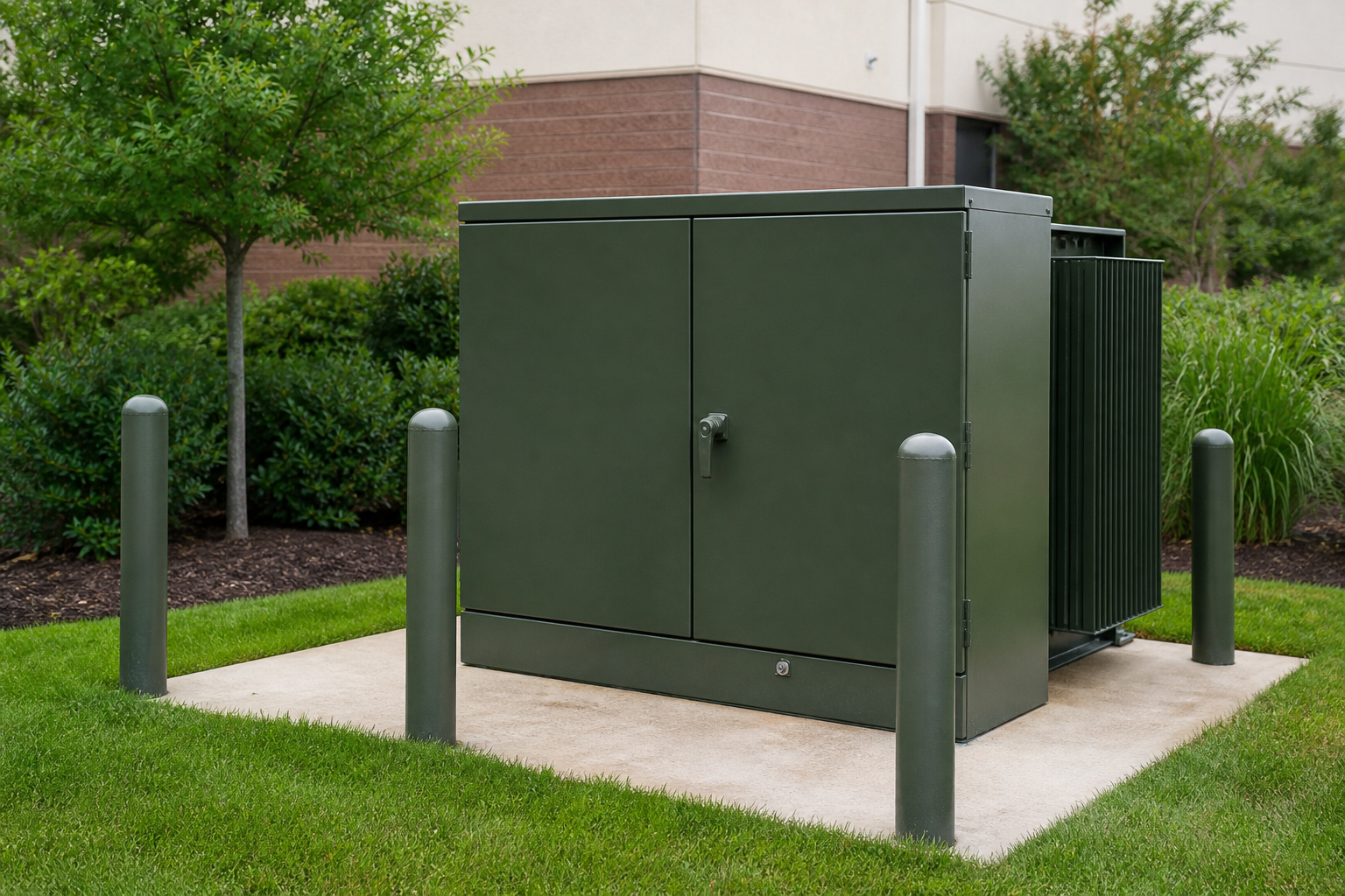
Three-phase pad-mounted transformers combine the transformer and tamper-resistant cable compartments in an outdoor ground-level installation.
Start with the distribution system, not the cabinet size
A three-phase pad-mounted transformer is commonly used in underground distribution systems for commercial developments, industrial sites, renewable-energy facilities and utility networks. Its appearance is familiar, but the correct configuration depends on the electrical system and the utility interface. Selecting only by kVA can lead to incompatible bushings, protection, switching or cable space.
The selection process should begin with the primary network arrangement, then confirm rating, voltage, grounding, protection, site conditions and maintenance access. IEEE C57.12.34 is commonly referenced for three-phase compartmental-type pad-mounted distribution transformers, while utility specifications may add detailed interface requirements.
Radial feed or loop feed
A radial-feed arrangement supplies the transformer from one incoming primary circuit. It is straightforward and suitable where the network does not need to continue through the transformer location. A loop-feed arrangement provides incoming and outgoing primary connections so the circuit can continue to another point. This may support utility switching and service-restoration practices, but the exact operating method is defined by the network owner.
The feed arrangement changes the high-voltage compartment layout, bushing wells, switching devices and cable clearances. The RFQ should therefore state radial or loop feed and include the utility’s preferred bushing and switching configuration.
Select kVA from the real load profile
Connected load is not the same as transformer demand. Review diversified demand, motor starting, harmonic-producing loads, expected growth and the daily load pattern. Oversizing can reduce utilization and increase first cost, while undersizing can increase temperature and shorten service life. For renewable or cyclic loads, provide the operating profile instead of a single peak value.
If units will operate in parallel, the vector group, voltage ratio, tap position and impedance need coordinated review. A future expansion plan should be included even when only one unit is being purchased now.
Voltage, grounding and basic insulation data
State the primary voltage class, nominal primary voltage, secondary voltage, frequency, phase and grounding arrangement. Also identify the required basic impulse insulation level and neutral arrangement. Utility systems may use different primary interfaces and protection practices even at the same nominal voltage, so the destination utility specification is important.
Protection and switching
Pad-mounted transformers may include internal fusing, bayonet-type protection, current-limiting fuses, loadbreak or deadbreak interfaces, switches and accessories according to the design. These are not interchangeable labels. The protection must coordinate with the upstream network, transformer inrush, downstream fault duty and the utility’s maintenance practice.
Ask the supplier to provide a clear component schedule and one-line representation. Protection selections should be confirmed during technical review rather than inferred from a product photograph.
Cable compartments and site layout
Confirm the number, size, material and bending radius of primary and secondary cables. The compartment must allow safe termination and maintenance access. Cable entry normally comes from below, so the concrete pad opening and conduit positions must match the approved transformer drawing.
The site plan should address working clearance, ventilation, bollards, drainage, finished ground level and access for installation or replacement. The transformer should not be placed where doors cannot fully open or where vehicles, floodwater or landscaping obstruct safe access.
Enclosure and environment
Outdoor equipment needs an enclosure and coating system appropriate for the local environment. Provide ambient temperature, altitude, humidity, coastal or industrial pollution exposure, seismic requirement and any special color or finish. Tamper resistance does not remove the need for controlled siting and local safety clearances.
What buyers should request before approval
Request the outline drawing, compartment arrangement, one-line diagram, nameplate schedule, terminal data, accessory list, losses, impedance and test plan. Confirm the concrete pad and conduit plan only after the manufacturer’s approved drawing is available. For repeat projects, retain the approved interface data as the baseline for future units.
Selection summary
A reliable pad-mounted transformer specification connects network operation with physical installation. Define radial or loop feed, load duty, voltage, grounding, protection, cable interfaces and site conditions as one coordinated package. Apex Electrics can organize these inputs and prepare the technical clarification required for product selection and quotation.
|
Suggested CTA Share the utility specification, load schedule and preliminary site layout to review the correct three-phase pad-mounted transformer configuration. |