EN
EN

Solar MV Step-Up Station
Solar MV Step-Up Station is configured to the purchaser's network, load and site requirements. The typical range below is for product-page reference; final guaranteed values are confirmed in the approved technical schedule.
|
RATED VOLTAGE |
RATED CAPACITY |
|
STANDARDS BASIS |
TYPICAL APPLICATION |
- Overview
- Recommended Products
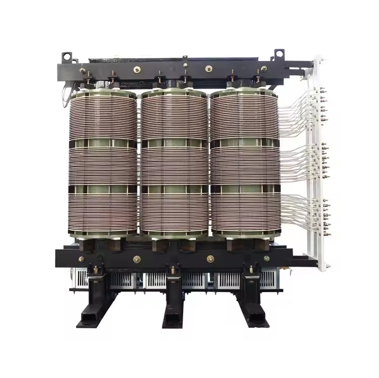
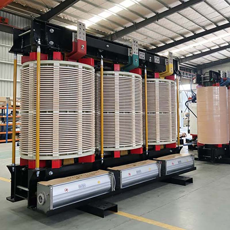
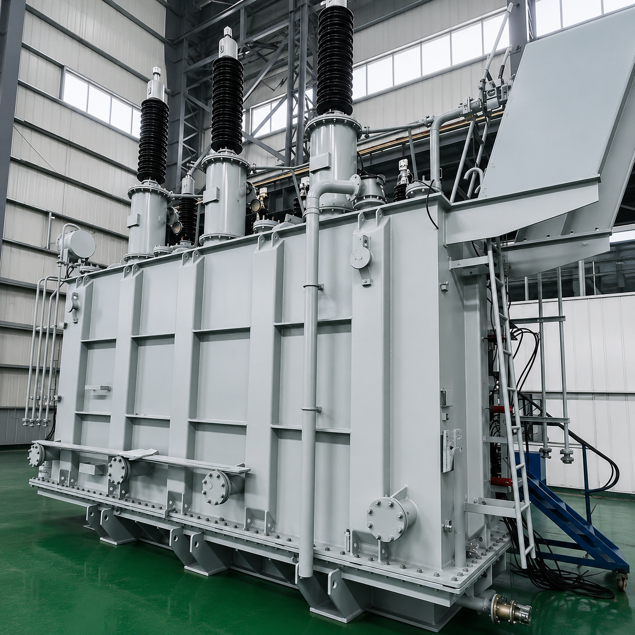
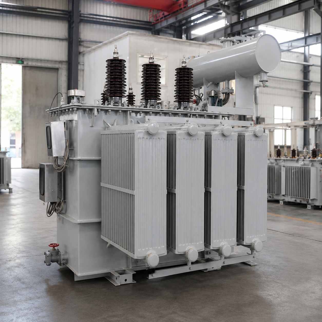
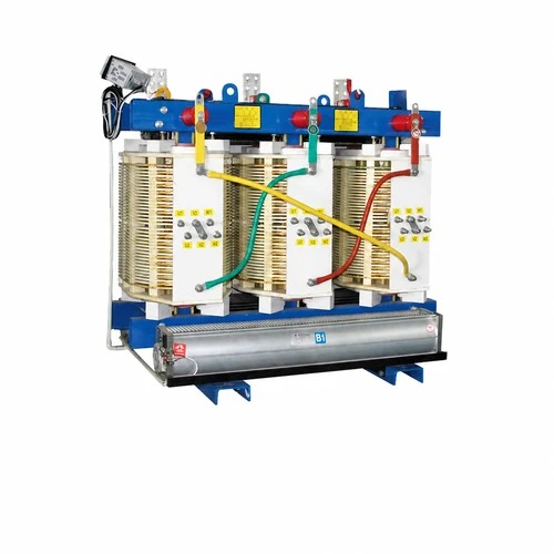
- Oil-immersed or dry-type transformer.
- RMU.
- protection and monitoring.
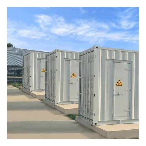
- skid, compact-station or container construction.
- Plant capacity, inverter type/output and collector-system voltage.
- Grid-connection voltage, grid code and approved single-line diagram.
- Required equipment boundary, protection/SCADA and auxiliary systems.
- Site conditions, delivery schedule, local installation scope and document list.
- Oil-immersed or dry-type transformer.
- RMU.
- protection and monitoring.
- skid, compact-station or container construction.
- Utility-scale photovoltaic plants.
- Solar collector and MV step-up systems.
- Grid-connection and plant auxiliary power packages.
Appurtenance
Inquiry
Please provide the following information so the product selection and quotation can be prepared accurately:
Overview
General Product Overview
The solar MV step-up station combines the inverter interface, step-up transformer, medium-voltage switchgear and auxiliary systems in one coordinated block. The design is based on inverter output, collector voltage, harmonic spectrum, cyclic loading and site conditions.
Main Technical Specifications
Parameter |
Typical range / configuration basis |
Rated voltage |
Inverter LV output to 20/33/35 kV |
Rated capacity |
1-10 MVA per block typical |
Frequency |
50 Hz or 60 Hz; utility-specific where applicable |
Standards basis |
IEC 60076, IEC 62271 and grid requirements |
Electrical interfaces |
PV/inverter, LV, MV collector and grid-connection interfaces |
Protection and control |
Protection, metering, SCADA and communication by grid requirements |
Deliverables |
Equipment schedule, drawings, data sheets and agreed test documents |
Delivery scope |
Procurement and coordinated delivery; site construction by the agreed local partner |
Project Scope and Interface Coordination
The package boundary is defined around the inverter output, collector network and grid-connection point. Interface schedules are used to coordinate ratings, protection, communication, auxiliary power, drawings and delivery batches across the selected equipment.
Main Applications
Central- or string-inverter photovoltaic power blocks.
Engineering Support
Apex supports requirement review, product selection, drawing and interface coordination, manufacturing follow-up, inspection/test-document coordination, export packing and delivery planning. The final scope is defined in the quotation and approved technical agreement.
Recommended Products
Utility-Scale Solar EPC Equipment Package | Solar Grid-Connection Substation Package | 33/35 kV Oil-Immersed Distribution Transformer