 EN
EN

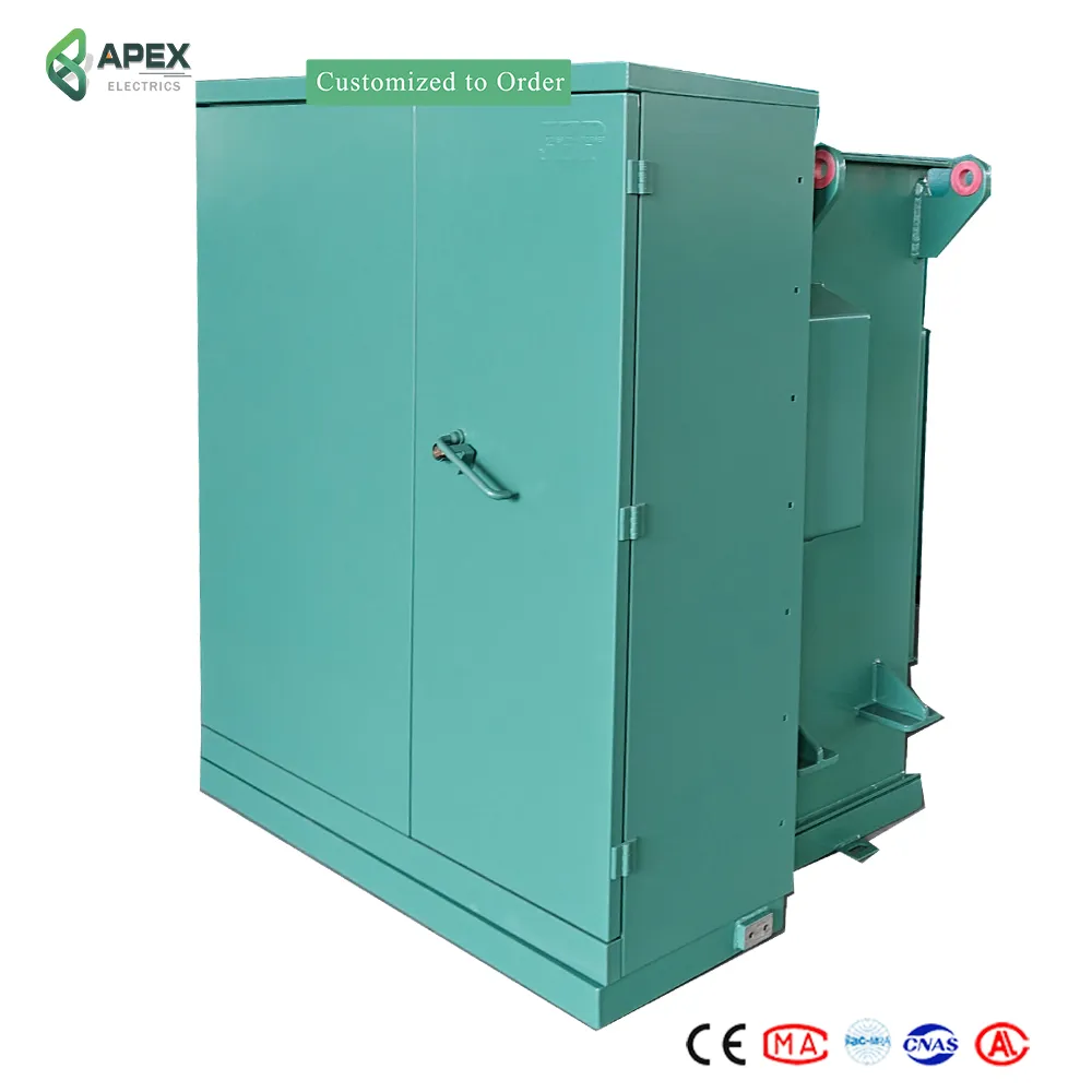
What Is a Three-Phase Transformer and Why It Matters
A three-phase transformer is an electromagnetic device that transfers electrical energy between three-phase circuits using magnetic induction. It steps voltage up or down while maintaining balanced power across three alternating phases—each separated by 120 degrees. Unlike a bank of three single-phase units, a single three-phase transformer delivers equivalent power in a more compact, cost-effective, and efficient package. This design makes it indispensable for industrial plants, utility substations, and power generation systems where continuous, balanced power delivery is critical. Because the three waveforms overlap, total instantaneous power remains nearly constant—reducing voltage fluctuations and improving equipment reliability. Three-phase transformers also provide electrical isolation and support flexible delta or wye configurations to align with grid or load requirements. Their superior efficiency—achieved through shared magnetic paths and optimized material use—translates directly into lower operational costs and smaller physical footprints.
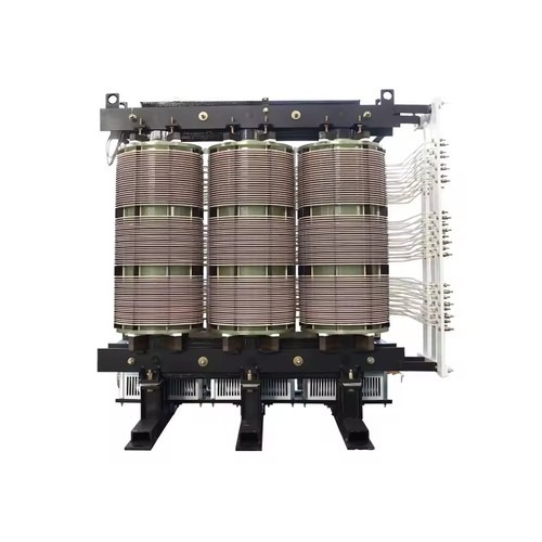
Core Construction and Working Principles of Three-Phase Transformers
Three-phase transformers form the backbone of industrial and utility power systems, efficiently converting large amounts of energy using a unified magnetic structure. Unlike banks of single-phase units, true three-phase designs integrate all elements into a single oil-filled tank housing a laminated magnetic steel core and corresponding windings. Primary construction variations include the compact three-limb core-type, widely used for applications up to 765 kV, and the flux-controlled five-limb shell-type, preferred for heavy industrial duty. Both share essential components: HV/LV bushings, on-load tap changers for voltage regulation, and advanced cooling systems to manage thermal stress.
Delta vs. Wye Configurations
Winding interconnection determines compatibility with grid architecture and load requirements. The table below summarizes key characteristics:
| Configuration | Voltage Relationship | Current Relationship | Common Use Cases |
|---|---|---|---|
| Delta (Δ) | Line voltage = Phase voltage | Line current = √3 × Phase current | Industrial motors, high-voltage transmission |
| Wye (Y) | Line voltage = √3 × Phase voltage | Line current = Phase current | Commercial building distribution, neutral-required systems |
| Delta-Wye | Step-down capability | Provides 30° phase shift | Utility substations, data center power distribution |
Delta configurations suit balanced three-wire systems without neutral currents; Wye connections enable safer, grounded-neutral systems common in commercial infrastructure. Both optimize material usage and efficiency while supporting stable, balanced power transfer.
Magnetic Coupling and Voltage Transformation Logic
A three-phase transformer operates via electromagnetic induction applied simultaneously across all three phases. AC current in the primary windings generates synchronized, time-varying magnetic fields within the shared core. This flux links continuously to the secondary windings, inducing proportional voltages governed by each phase’s turns ratio. Balanced magnetic coupling minimizes core vibration and flux distortion—ensuring consistent transformation efficiency and long-term mechanical integrity. Losses are inherently lower than equivalent single-phase setups due to shared magnetic paths and reduced conductor and core material requirements.
Key Performance Metrics and Selection Criteria for Three-Phase Transformers
Selecting the right three-phase transformer requires evaluating metrics that balance capital investment against lifetime performance. Engineers must match technical specifications to load profiles, environmental conditions, and system integration needs.
KVA Rating, Efficiency, and Impedance Considerations
The KVA rating must accommodate the continuous load—including anticipated growth—without oversizing, which degrades part-load efficiency. Modern units meeting IEEE C57.12.00 or IEC 60076 standards achieve efficiencies exceeding 99% at full load, significantly reducing total cost of ownership over decades of operation. Impedance—typically 4% to 8% for distribution units and 10% to 15% for generator step-up transformers—governs voltage regulation under dynamic loads and ensures proper coordination with protective devices during faults.
Cooling Methods and Insulation Classes
Thermal management defines service life and reliability. Natural convection methods like ONAN (Oil Natural Air Natural) suit moderate-duty applications, while forced-air (ONAF) or forced-oil/forced-air (OFAF) systems extend capacity in space-constrained or high-ambient environments. These cooling approaches pair with insulation classes—Class B (130°C), Class F (155°C), or Class H (180°C)—which specify maximum allowable hotspot temperatures. Selecting the correct combination prevents premature insulation degradation and supports extended maintenance intervals in demanding industrial settings.
Real-World Applications and Industry-Specific Use Cases
Three-phase transformers serve as foundational components in modern power distribution networks—enabling efficient, low-loss transmission across vast distances and diverse terrains. Their ability to maintain balanced loading and deliver high power density makes them essential for integrating renewable generation and sustaining mission-critical infrastructure.
Power Distribution Networks and Renewable Integration
Utilities rely on three-phase transformers for their proven reliability, harmonic mitigation, and fault-current handling—especially when feeding dense urban loads. Delta configurations excel in managing asymmetric industrial demand, while wye-connected units support safe grounding practices in substation environments. Offshore wind platforms deploy marine-grade, encapsulated variants resistant to salt corrosion; field data from the Offshore Wind Operations Report 2024 indicates median service lifespans exceeding 15 years under saline exposure.
Industrial Manufacturing and Data Center Infrastructure
High-density manufacturing operations use three-phase transformers to supply precision power to induction furnaces, rolling mills, and automated assembly lines—where voltage stability and low impedance are critical for synchronous motor performance and torque consistency during rapid cycling. Tier-4 data centers specify liquid-filled, K-class insulated units for enhanced fire resistance and thermal resilience, often deployed alongside N+1 redundant Automatic Transfer Switches (ATS) to sustain uptime during brownouts or grid disturbances.
FAQ
Q: What is the main advantage of a three-phase transformer over single-phase units?
A: A three-phase transformer delivers equivalent power in a more compact, cost-effective, and efficient package, reducing operational costs and improving reliability.
Q: What are the key configurations of three-phase transformers?
A: The main winding configurations are Delta (Δ), Wye (Y), and Delta-Wye, each suited to different applications like industrial motors or commercial building distribution.
Q: Why is thermal management critical for three-phase transformers?
A: Proper thermal management prevents premature insulation degradation, extends service life, and ensures consistent operation under high-demand conditions.
Q: How are three-phase transformers used in renewable energy systems?
A: They integrate renewable generation efficiently by maintaining balanced loads, reducing transmission losses, and handling fault currents in challenging environments like offshore platforms.
Q: What factors should engineers consider when selecting a three-phase transformer?
A: Engineers should assess KVA rating, efficiency, impedance, cooling methods, and insulation classes to match specific load and environmental conditions.