 EN

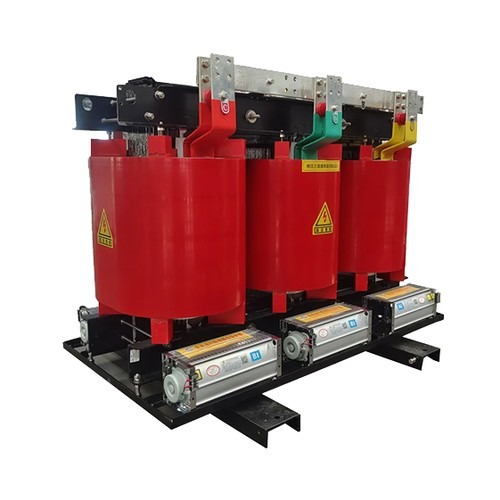
Optimizing Dry Type Transformer Efficiency in 2026
? Key Takeaway: Commercial facilities, renewable installations, and urban distribution hubs facing strict 2026 decarbonization mandates must optimize their dry type transformer fleets across both core metallurgy and dynamic thermal parameters. Investing in high-grade magnetic cores and precision vacuum casting delivers a rapid return on investment by suppressing continuous no-load losses, establishing the modern dry type transformer as an indispensable foundation for low-loss power distribution.
Regulatory Pressures and Modern Efficiency Benchmarks in Power Distribution
Rapid global electrification and aggressive grid decarbonization targets in 2026 have pushed power distribution efficiency into sharp focus. Across North America, Europe, and Asia-Pacific markets, electrical engineering mandates dictate strict thermodynamic and electromagnetic losses for indoor distribution equipment. Regulatory standards, including European Ecodesign Tier 2 (EN 50541 / EU 2019/1781), US Department of Energy (DOE) conservation standards, and IEC 60076-11 specifications, enforce stringent limits on both no-load and full-load losses. Within commercial high-rises, underground transit networks, and high-density manufacturing plants, safety considerations eliminate oil-filled units due to catastrophic explosion and contamination risks. Consequently, deploying an energy-optimized dry type transformer represents the primary method for reconciling mandatory fire safety compliance with aggressive net-zero emissions targets. Electrical planners who specify an advanced dry type transformer must balance regional statutory compliance against operating load profiles. In modern indoor substations where units remain energized continuously, minimizing baseline losses within the dry type transformer structure prevents thousands of kilowatt-hours in thermal waste each year. Engineering teams prioritizing dry type transformer efficiency ensure regulatory compliance while safeguarding substations against escalating industrial electricity tariffs.
Electromagnetic Core Metallurgy and Stray Loss Reduction Strategies
Minimizing energy waste in an industrial dry type transformer begins at the magnetic core, which generates continuous excitation losses twenty-four hours a day regardless of connected electrical load. Core losses comprise magnetic hysteresis and induced eddy currents within the structural laminations. To curb these unyielding losses, premier dry type transformer designs incorporate high-permeability, domain-refined cold-rolled grain-oriented (CRGO) silicon electrical steel or innovative amorphous metal ribbons. Advanced fabrication utilizes step-lap mitered core stacking geometries instead of conventional butt-lap joints, drastically smoothing magnetic flux trajectories at limb corners and reducing excitation current spikes. This refined magnetic configuration curbs localized saturation, cutting no-load dissipation across the dry type transformer by fifteen to twenty-five percent compared to legacy distribution infrastructure. Furthermore, precision laser scribing restrains magnetic domain wall velocity, which dampens high-frequency eddy dissipation throughout the dry type transformer core structure. Stray magnetic flux management is reinforced by non-magnetic clamping hardware and slotted structural channels that prevent parasitic circulating currents. By implementing these metallurgical and structural controls, the resulting dry type transformer maintains cool, quiet electromagnetic conversion while delivering sustained energy savings.
Coil Conductor Geometry and Advanced Solid Dielectric Insulation Systems
While core optimization addresses continuous standby losses, load-dependent copper losses ($I^2R$) govern overall dry type transformer performance under heavy operational loading. Total winding loss consists of direct ohmic resistance along with additional skin and proximity effects triggered by alternating electromagnetic fields. Premium dry type transformer engineering replaces loose round-wire windings with precision electrolytic copper or high-conductivity electrical-grade aluminum foil. Foil winding construction spreads electrical current evenly across the coil width, virtually eliminating axial mechanical stresses during external short-circuit events while lowering high-frequency eddy resistance within the dry type transformer windings. The choice of dielectric insulation system further dictates thermal dissipation and electrical endurance. Cast resin dry type transformer (CRT) units encapsulate high-voltage coils in epoxy resin blended with silica flour under vacuum casting, forming a void-free, moisture-impervious solid envelope with partial discharge levels below ten picocoulombs. Alternatively, vacuum pressure impregnated (VPI) designs utilize Class H or Class C aramid paper composites capable of enduring 180°C to 220°C hot-spot temperatures. Integrating robust insulation materials prevents thermal breakdown, allowing the dry type transformer to sustain high dielectric integrity without incurring prohibitive cooling penalties.
Harmonic Loading and Thermal Management in Critical Infrastructure
The proliferation of non-linear electrical loads—including variable frequency drives, uninterruptible power supply systems, electric vehicle superchargers, and artificial intelligence server racks—introduces severe harmonic distortions that degrade dry type transformer performance. High-order harmonic currents dramatically elevate winding eddy losses proportionally to the square of the harmonic frequency, triggering localized hot spots and reducing effective service life. In response, modern facilities require a K-factor rated dry type transformer designed with transposed parallel conductors and electrostatic copper shielding between primary and secondary windings to dissipate stray capacitive noise. Efficient thermal management plays an equally decisive role in protecting dry type transformer efficiency. While natural convection (AN) cooling provides silent, maintenance-free operation under normal industrial cycles, pairing digital temperature controllers with forced-air (AF) cross-flow blowers boosts continuous dry type transformer load capacity by thirty-three to fifty percent during peak operational demand. Real-time temperature sensors embedded directly within the low-voltage windings communicate via standard industrial protocols, enabling facility managers to monitor dry type transformer winding temperature rises and dynamically adjust load balancing before thermal penalties degrade system efficiency.
Empirical Performance Comparison Across Standard Distribution Ratings
Evaluating the true economic value of a high-efficiency dry type transformer requires calculating the total cost of ownership (TCO) across its operational life rather than focusing solely on upfront acquisition expense. The operational load point is critical: peak operating efficiency for an industrial dry type transformer typically occurs between forty and sixty percent of rated capacity, which closely mirrors average daily distribution loads. Operating significantly below or above this optimal load curve compounds either fixed excitation losses or exponential resistive losses. The performance matrix below details typical 50/60 Hz performance baselines for a three-phase cast resin dry type transformer engineered to Tier 2 international standards:
| Rated Capacity (kVA) | Voltage Class (kV) | No-Load Core Loss (W) | Full-Load Copper Loss (W) | Full-Load Efficiency (%) | 50% Load Efficiency (%) |
|---|---|---|---|---|---|
| 500 | 11 / 0.4 | 1,150 | 4,800 | 98.83% | 99.08% |
| 1,000 | 11 / 0.4 | 1,950 | 8,500 | 98.96% | 99.20% |
| 1,600 | 11 / 0.4 | 2,750 | 12,800 | 99.04% | 99.27% |
| 2,000 | 11 / 0.4 | 3,300 | 15,200 | 99.08% | 99.30% |
| 2,500 | 11 / 0.4 | 3,900 | 18,500 | 99.11% | 99.32% |
Empirical testing proves that a premium dry type transformer achieves maximum efficiency near the fifty percent load threshold. Selecting the appropriate frame size ensures that the installed dry type transformer operates within this sweet spot, minimizing ongoing electrical losses and maximizing capital returns over decades of service.
Factory Acceptance Verification and Global Supply Chain Execution
Securing long-term electrical reliability requires certified factory validation and transparent manufacturing traceability rather than unverified commercial claims. Comprehensive factory acceptance testing (FAT) for a newly constructed dry type transformer must verify winding resistance, voltage transformation ratio, short-circuit impedance, and sound pressure levels in accordance with IEC 60076-11 and IEEE C57.12.01 protocols. Essential quality audits include routine partial discharge tests conducted in shielded screening chambers, confirming that the cast coil dry type transformer exhibits partial discharge below ten picocoulombs to prevent insulation aging. Advanced manufacturing facilities operated by APEX integrate automated CNC coil winding, computerized vacuum potting autoclaves, and rigorous high-voltage test laboratories to ensure every production dry type transformer strictly satisfies international efficiency baselines. Combining robust industrial fabrication with turnkey containerized logistics and comprehensive technical documentation, APEX delivers certified dry type transformer solutions engineered for high-uptime data centers, renewable substations, and critical urban utilities worldwide.
Table of Contents
-
Optimizing Dry Type Transformer Efficiency in 2026
- Regulatory Pressures and Modern Efficiency Benchmarks in Power Distribution
- Electromagnetic Core Metallurgy and Stray Loss Reduction Strategies
- Coil Conductor Geometry and Advanced Solid Dielectric Insulation Systems
- Harmonic Loading and Thermal Management in Critical Infrastructure
- Empirical Performance Comparison Across Standard Distribution Ratings
- Factory Acceptance Verification and Global Supply Chain Execution