EN

5 MVA Dual Low Voltage Winding Transformer for Nigeria
Oil-Immersed Step-Up Transformer for an Equipment Replacement Project
APEX TECHNOLOGIES recently secured an order for a 5 MVA oil-immersed step-up transformer for an equipment replacement project in Nigeria. The specified configuration comprises an 11 kV winding and two 0.4 kV low-voltage windings, with copper conductors and the required transformer accessories, including a Buchholz relay.
A key project requirement was the low-voltage incoming cable connection: 32 single-core cables, each with a conductor cross-sectional area of 500 mm², arranged as eight parallel cables for each of phases A, B and C and eight for neutral N.
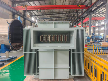
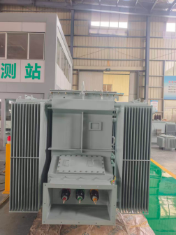
Figure 1. Workshop view of the transformer with the terminal compartment open.
|
Project Location |
Nigeria |
|
Application |
Replacement of existing equipment |
|
Rated Power |
5 MVA |
|
Transformer Type |
Oil-immersed step-up transformer |
|
Winding Arrangement |
One 11 kV winding and two 0.4 kV low-voltage windings |
|
Winding Material |
Copper |
|
Cable Requirement |
32 × 500 mm² single-core cables; eight each for A, B, C and N |
|
Accessory Scope |
Required transformer accessories, including a Buchholz relay |
Project Requirements and Equipment Configuration
Replacement Project Background
The customer required a transformer to replace existing equipment in Nigeria. In addition to the 5 MVA rating and voltage arrangement, the purchase specification included a defined incoming cable configuration. The transformer requirement therefore covered both electrical performance and the physical connection interface with the customer’s cable system.
Dual Low-Voltage Winding Arrangement
The transformer was specified for step-up service, with two 0.4 kV low-voltage windings and an 11 kV winding. Copper windings were required, together with the associated transformer accessories. The Buchholz relay was explicitly included in the accessory requirement.
This dual low-voltage winding arrangement distinguishes the project from a conventional transformer with a single low-voltage winding. The voltage configuration, winding material and accessory scope formed the principal equipment requirements for the replacement order.
Connection for 32 Single-Core Cables
The customer specified eight parallel 500 mm² single-core cables for each of phases A, B and C, together with eight cables of the same cross-section for neutral N. The stated incoming connection requirement therefore comprised 32 cables in total.
The number and cross-section of the cables made the low-voltage connection interface a significant part of the project. For a replacement application, this level of detail links the transformer specification to the cable arrangement at the installation, rather than defining the equipment solely by its rated power and voltage ratio.
Workshop and Packing Documentation
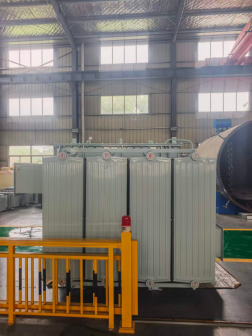
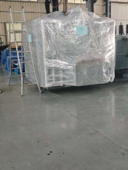
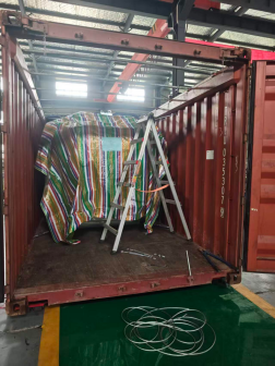
Project photographs show the transformer in the workshop, including views of its terminal compartments and radiator assemblies. Additional photographs record the equipment after protective wrapping and during container-loading preparation. The photographic record covers workshop and packing activities; site commissioning and operating results are outside the scope of this case study.
Project Highlights
- 5 MVA oil-immersed transformer specified for replacement service in Nigeria.
- One 11 kV winding and two 0.4 kV low-voltage windings for step-up operation.
- Copper windings and the required accessory package, including a Buchholz relay.
- Customer-specified incoming connection for 32 single-core 500 mm² cables.
Replacement Transformer Inquiries
For a replacement transformer inquiry, contact APEX TECHNOLOGIES with the existing equipment nameplate, required voltage arrangement and cable connection details. Terminal photographs and available outline or connection drawings help establish the interface requirements at the quotation stage.
Project Photographs
|
Figure 2. Transformer workshop view showing the terminal compartment and radiator assemblies. |
Figure 3. Side view of the radiator assemblies. |
|
Figure 4. Transformer after protective wrapping in the workshop. |
Figure 5. Covered equipment inside an open-top container during loading preparation. |