 EN
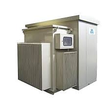
How a High Voltage Step Down Transformer Works
Turns Ratio and Voltage Reduction Fundamentals
A high voltage step down transformer reduces voltage by using fewer turns on the secondary winding than on the primary. The relationship is governed by the turns ratio formula: Vs = (Ns ÷ Np) × Vp, where Np and Ns are the numbers of primary and secondary turns, and Vp is the primary voltage. Since Ns < Np, the secondary voltage Vs is always lower than Vp. For example, a 10:1 unit supplied with 4,160 V delivers 416 V at the secondary.
In an ideal transformer, power remains nearly constant—so stepping down voltage proportionally increases current. A 10 A primary current becomes 100 A on the secondary under a 10:1 reduction. This inverse voltage–current relationship dictates that secondary-side components—including conductors, bushings, and overcurrent protection—must be rated for higher current density and thermal stress. Selecting the correct turns ratio therefore requires aligning available high-side voltage with required low-side voltage while accounting for load current, voltage regulation, and short-circuit withstand capability.
Core Physics: Faraday’s Law and Magnetic Coupling in HV Step-Down Operation
Operation hinges on Faraday’s Law of Electromagnetic Induction: alternating current in the primary winding generates a time-varying magnetic flux in the core, which couples to the secondary winding via a low-reluctance path. The induced electromotive force in each winding follows E = N × dΦ/dt, meaning voltage is directly proportional to both turn count and the rate of change of flux.
Because the secondary has fewer turns, it develops a proportionally lower voltage. In practice, coupling is never perfect—leakage flux and winding resistance cause small voltage drops under load. Core material and geometry critically influence efficiency, saturation limits, and thermal behavior. Laminated silicon steel minimizes eddy-current losses; grain-oriented steel further enhances flux density capacity. Core saturation—triggered by excessive voltage, frequency deviation, or DC bias—causes sharp rises in magnetizing current and risks insulation failure. Robust magnetic design therefore balances flux density, core cross-section, and winding layout to sustain stable transformation across dynamic load and transient conditions.
Key Selection Criteria for High Voltage Step Down Transformers
Power Rating, Load Profile Matching, and Thermal Derating
Sizing begins with kVA = (Volts × Amps) / 1,000. Accurately assess peak and average load profiles—and include a 20–30% margin for future expansion, especially in industrial and data center applications. Oversizing raises no-load losses and capital cost; undersizing accelerates insulation aging and compromises reliability.
Thermal derating is essential because nameplate ratings assume standard ambient conditions—typically 30°C—and defined temperature rise classes (e.g., 80°C, 115°C, or 150°C for dry-type units). Lower-rise designs extend insulation life but may require larger physical footprints. Efficiency should be verified at 35%, 50%, and 100% load per DOE 2016 and IEC 60076-20, and 15-minute demand interval data should inform conductor sizing and overcurrent coordination per NEC 2023.
For installations above 30°C ambient or at altitude, apply manufacturer-specified derating—commonly 0.4% per °C above 30°C for dry-type units. Nonlinear loads introduce harmonic currents that increase stray and eddy-current losses; such applications warrant K-rated construction (e.g., K-13) or appropriate de-rating of standard units per IEEE C57.110-2018.
Frequency Compatibility and Harmonic Mitigation
Transformers must operate at system frequency—typically 50 Hz or 60 Hz. Operating below rated frequency increases core flux density, risking saturation, excessive magnetizing current, and overheating. Units feeding variable-frequency drives, UPS systems, or rectifier-based loads face significant harmonic distortion.
Harmonic currents elevate winding losses and accelerate thermal degradation. IEEE C57.110-2018 provides guidance for de-rating standard transformers under nonlinear loading. K-factor ratings (K-4, K-13, K-20) match construction robustness to expected harmonic spectra. Alternatively, harmonic-mitigating transformers use phase-shifting or zig-zag secondaries to cancel triplen harmonics (3rd, 9th) and reduce 5th/7th order content. To prevent resonance and nuisance tripping, verify voltage total harmonic distortion (THDv) at the point of common coupling complies with IEEE 519-2022 limits—typically ≤5% for general systems.
Safety and Compliance Requirements for High Voltage Step Down Transformers
Safety starts with compliance to international and regional insulation coordination standards—including IEC 60076 and IEEE C57—ensuring dielectric integrity under normal and abnormal conditions. Basic Impulse Level (BIL) rating, expressed in kV peak, defines the transformer’s ability to withstand lightning and switching surges without flashover or insulation failure. Higher BIL values improve resilience in exposed substation environments.
BIL Ratings, Grounding Configurations, and Arc-Flash Mitigation
Grounding strategy directly influences fault current magnitude and overvoltage behavior. Solidly grounded systems limit transient overvoltages but produce high ground-fault currents; impedance grounding restricts fault current but demands precise insulation coordination. NFPA 70E mandates arc-flash risk assessments and appropriate PPE selection. Where feasible, keep incident energy below 8 cal/cm² through remote operation, current-limiting fuses or breakers, and arc-resistant switchgear.
Complement these measures with routine maintenance: insulation resistance testing (per IEEE 43), infrared thermography, and—where applicable—dissolved gas analysis (DGA) for oil-filled units. These practices verify ongoing dielectric strength and thermal integrity, ensuring safe, reliable service life.
Real-World Applications of High Voltage Step Down Transformers
Substation Integration: From Transmission-Level HV (69–500 kV) to Medium-Voltage Distribution
In transmission substations, incoming lines operate at 69 kV to 500 kV. High voltage step down transformers reduce this to medium-voltage distribution levels—typically 4.16 kV to 34.5 kV—for onward delivery to commercial, industrial, and municipal networks. This stage limits downstream short-circuit current, enabling smaller, more economical switchgear and protection systems. On-load tap changers (OLTCs) maintain stable bus voltage despite load fluctuations.
A typical 230/69 kV substation uses a main transformer to step down from 230 kV to 69 kV for sub-transmission; additional units may generate 12.47 kV or 13.8 kV for local feeders. Three-phase configurations dominate due to superior efficiency, reduced footprint, and lower core losses. Units are typically installed in fenced bays with oil containment, surge arresters, and forced-oil or forced-air cooling systems.
Maintenance relies on real-time monitoring—including winding temperature, oil level, and DGA trends—as well as periodic thermographic scans. By siting step-down transformation near load centers, utilities minimize line losses, enhance voltage regulation, and improve overall service reliability.
FAQ
What is a high voltage step down transformer?
A high voltage step down transformer reduces high incoming voltage to a lower level for safe distribution and use.
How does the turns ratio affect voltage reduction?
The turns ratio, defined as Ns ÷ Np, determines the proportionate reduction of voltage between the primary and secondary windings.
What does thermal derating mean?
Thermal derating adjusts transformer capacity based on ambient temperature or altitudes exceeding standard ratings.
How do harmonic currents impact transformers?
Harmonic currents increase winding losses and thermal stress, requiring specialized designs or de-rating to mitigate effects.
What is the importance of BIL rating?
BIL (Basic Impulse Level) rating ensures transformers can withstand high surge events like lightning without insulation failure.